A quick romp through electronics, microcontrollers, and programming with the Arduino UNO
Introduction
This document aims to get you up and running with some programmable hardware so
that you can invent your own things that move and interact with the world, and
are reconfigurable and adaptive in what they do. It will consist of only
smatterings of knowledge for the various pieces because our goal is to get to
the point where you can play around on your own.
We focus on the Arduino UNO device, a self-contained microcontroller that is
prized for its easy-of-use, its open-source design, and the availability of
examples of web. As a microcontroller it includes a microprocessor and a little
bit of memory (to store programs and data), a USB connector, a separate power
connector, a clock, some blinking lights, and various other bits of circuitry
for interacting with the world (a.k.a. I/O circuits). Think of it as a cut down
computer (close to a programmable calculator), but specialized for connecting
stuff up to it. The Arduino is robust, so it'll be quite forgiving should things
be wired-up incorrectly.
I don't want to assume much background—so we'll go through the
bits and pieces of the hardware and software gently. Much of this tour
will be done in person, so the notes aren't intended to be complete by themselves. Instead, they have cues to take us through the various bits to make sure
we build-up in a logical sequence, learning things as we need them, and
nothing critical is omitted.
What you need to bring
Check that you have the following:
| A 9V Battery |
 |
| A USB Type B cable (e.g., for printers) |
 |
| Your laptop (it is worthwhile trying to install the arduino software, mentioned below.) |
 |
Inventory (what you'll be supplied with)
Check that you have the following:
| Arduino UNO |
 |
| A 9V wall adapter power supply |
 |
| A 9V battery leads |
 |
| Breadboard |
 |
| A few jumper wires |
 |
| Aligator leads |
 |
| A few resistors |
 |
| Four pin LED |
 |
| A micro button switch |
 |
| A potentiometer (variable resistor) |
 |
| A photoresistor |
 |
| A NPN-Type transistor |
 |
| A 30 cm length of flexinol/muscle wire |
 |
Before we begin...
Go to http://www.arduino.cc,
download and install the latest IDE for your computing platform. We will
continue with some preliminaries, that do not need to use the arduino yet.
Electronics basics
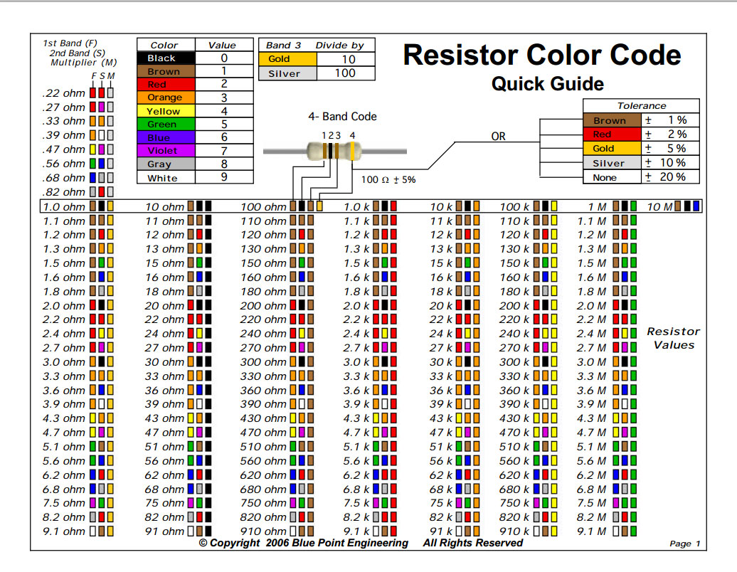
- Connect the LED to a 9V battery. This link shows how the colors work.
- It is better to connect the LED through a resistor. Ideally a 220 Ω resistor (look for color code in bands: red red brown gold). Here is a reference
This is a reference for how the color codes work. If you're lazy here's a list of the common
resistor sizes.
- A breadboard is quite useful for wiring components
with little fuss. See this image
describing how they work.
- Make a circuit with the micro button switch that turns the LED on/off.
- Make a circuit with the potentiometer in series with the LED.
During these exercises, cut to length and strip jumper wires as needed.
Arduino: First steps
- Take the arduino out of its box.
- Add the rubber feet to the bottom of the circuit board.
- Connect the arduino to your laptop via the USB cable.
- Also check that your wall adapter works when plugged in.
Arduino: Sensors and Input
Power, reading an analog value, the "Serial Monitor"
- Load the arduino software.
- Click File | Examples | 01.Basics | AnalogReadSerials
- Let's look at the code.
- See the initialization block and a loop function; variables, expressions, and comments.
- Click the verify button.
- Click the upload. (You might have to select the correct port in the Tools menu.)
- Look at the page associated with this example.
- Build the circuit on your breadboard.
- Test it.
Tweak the code
- Modify the code so that it prints "nothing" when the switch is to the left, and "some" when it is dialled to the middle, and "all" when it is to the right.
Generalize the hardware
- Modify your circuit to use the photoresistor. This
page shows
you how. Note the 10K Ω resistor (brown black orange gold).
- Test it. Pay attention to the range of values.
- Try the "Serial Plotter" tool too.
- Now modify your circuit to use the push button. (You should use a resistor.)
- Look at this diagram to figure out how to build the circuit.
- What readings do you get if you just hold the wire connected to the end of
the analog input in your hands?
- Now try connect the output wire to a digital input pin. Here is some code you can use to read from it.
Arduino: Outputs
Output pins
- Click File | Examples | 01.Basics | Blink
- Here is the associated page with the circuit.
- Build the circuit on your breadboard. What is the resistor for?
- Test it.
- Change it so it blinks a different color.
- Adjust the code to modify the blink timing so that it is on twice as long as it is off.
- Make it blink only three times then stop.
- Try disconnecting the USB cable.
- Change the output pin 13 to pin 9. (What changed?)
- Modify the code to make it signal S-O-S in morse code: • • • — — — • • •
- Modify the circuit and code so that it blinks green, blue, green, blue, green, blue, forever.
Flexinol, and amplification via a transistor
The output pins from your arduino are really intended as signals. They
aren't intended to do the heavy-lifting of actually powering components. When
the components are LEDs, then it's no sweat. But if we're actually going to be
moving things in the real world, we shouldn't be relying on
those output pins to provide the necessary power. And doing so can damage the
arduino, so try to avoid it.
What we need is to have a beefy flow of current, and a way to use the output
pin just to throw the switch to turn that flow on/off. That is what the
transistor component does.
This picture gives an all-in-one description of how your NPN transistor works.
This figure shows the schematic for your transistor and how relate this to physical component. We'll be connecting a
1K Ω resistor (brown black red gold)between the output pin and the base.
Be careful not to mix up the pins of your transistor: if you put an LED
in backwards the current simply doesn't flow (thats the Diode part). But if
you send all the power through the Base to the Emitter, it can destroy the
transistor.
- Start from the code that blinks the LED. Adjust it so that it
stays on for 3 seconds, then goes off for 5 seconds.
- Now build this circuit here.
- Make sure you've got your AC adapter plugged in and connected.
- Use the alligator leads to connect to your flexinol.
This is an example of "heavy-lifting" because the shrinkage comes from
heat. Current is turned into heat, affecting the physical properties of
the material. Once current is removed, the material cools by dissipating
the heat.
Input and output
- Can you make a circuit that changes its blinking rate as your turn the potentiometer?
- How would you make something that could show you whether you needed more light to read by? (Suppose it show a green light if it is O.K., but red when
you should turn on a reading lamp?)
- Revert to the circuit with a single color blinking. Now modify the circuit and code so that it blinks until you hit the push button.
Notes & Resources
The sources and copyright owners of various images are acknowledged in "alt" tags.
- The title is a shameless knockoff of Raymond W. Anderson's 1947 mathematics book.
- Because the arduino is so versatile, open-source, and requires the minimum background, it
is used by a great many DIY and hobbyists the world over. Just searching the
web can give you access to a wealth of examples:
- There's lots of expertise on internet fora who can help you get things
working, explain how to do something, why something isn't working, or give
constructive suggestions.
- Arduno Forum - Index
- Or use this as an excuse to make a friend with a student in Computer Science or Engineering!
- Finally, you can expand the capabilities of your Arduino through add-on modules called shields. Depending on what functionality you desire, these can be relatively inexpensive. Here are some places to see what is available: